REPEATER
THE REPEATER, FOR HOSTILE CONDITIONS
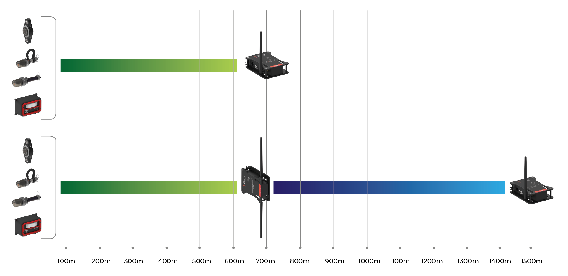
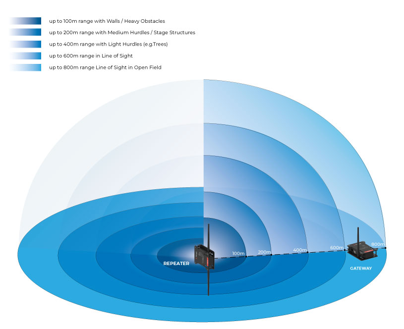
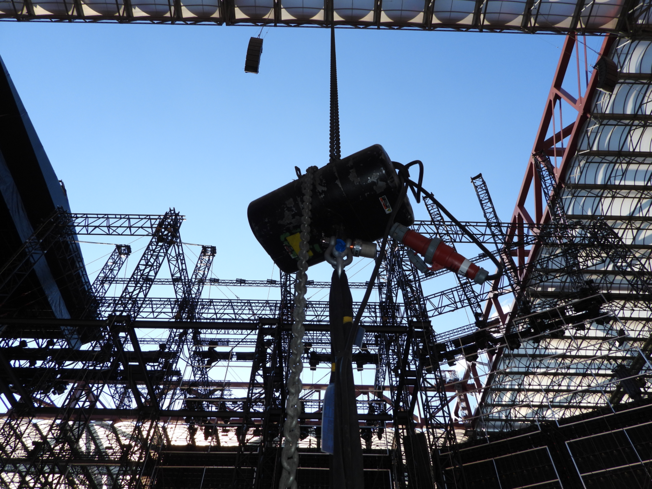
Each set up is different. To cover distances over 600m between cells and Gateway or when there are significant obstacles to overcome, it may be necessary to add one or more Repeaters.
THE MAIN INFORMATION DIRECTLY ON THE PANEL
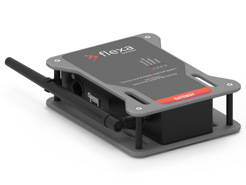
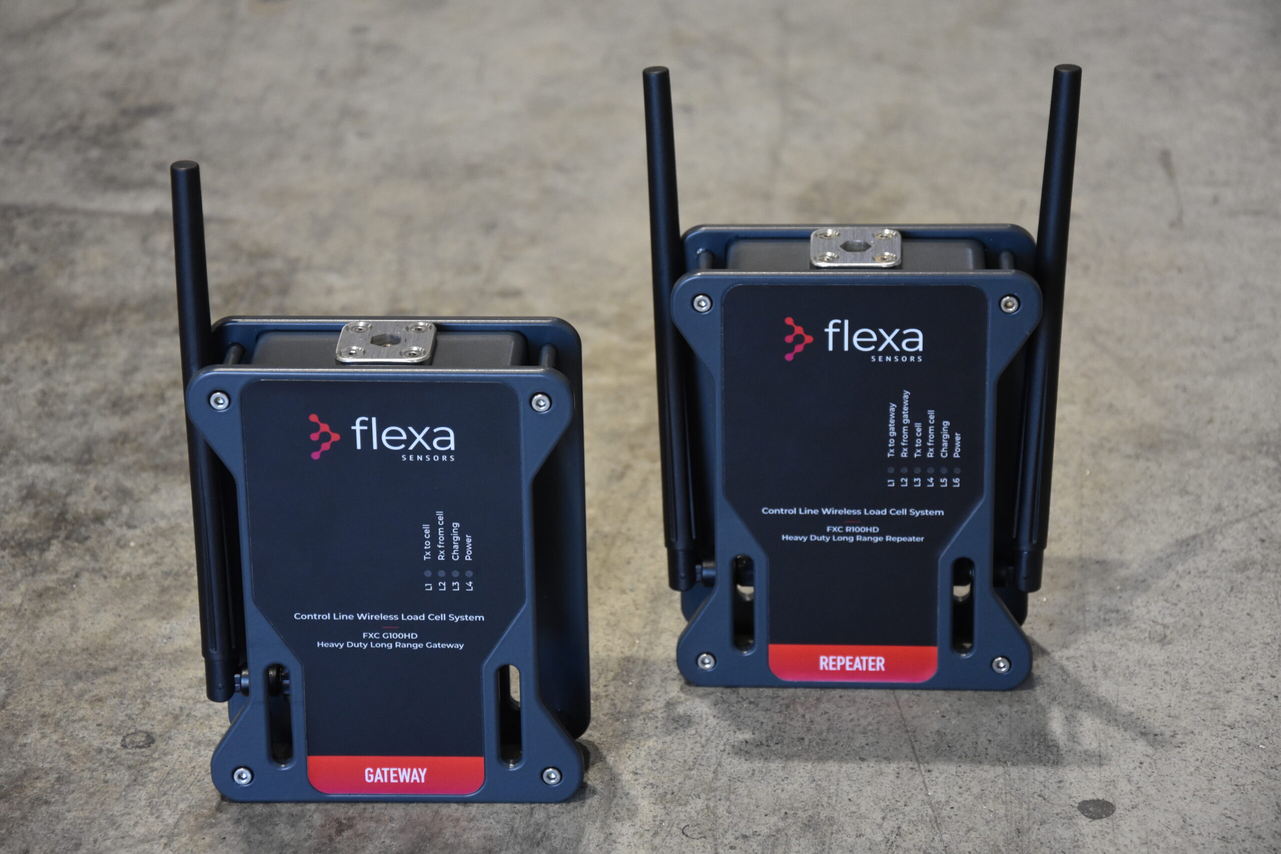
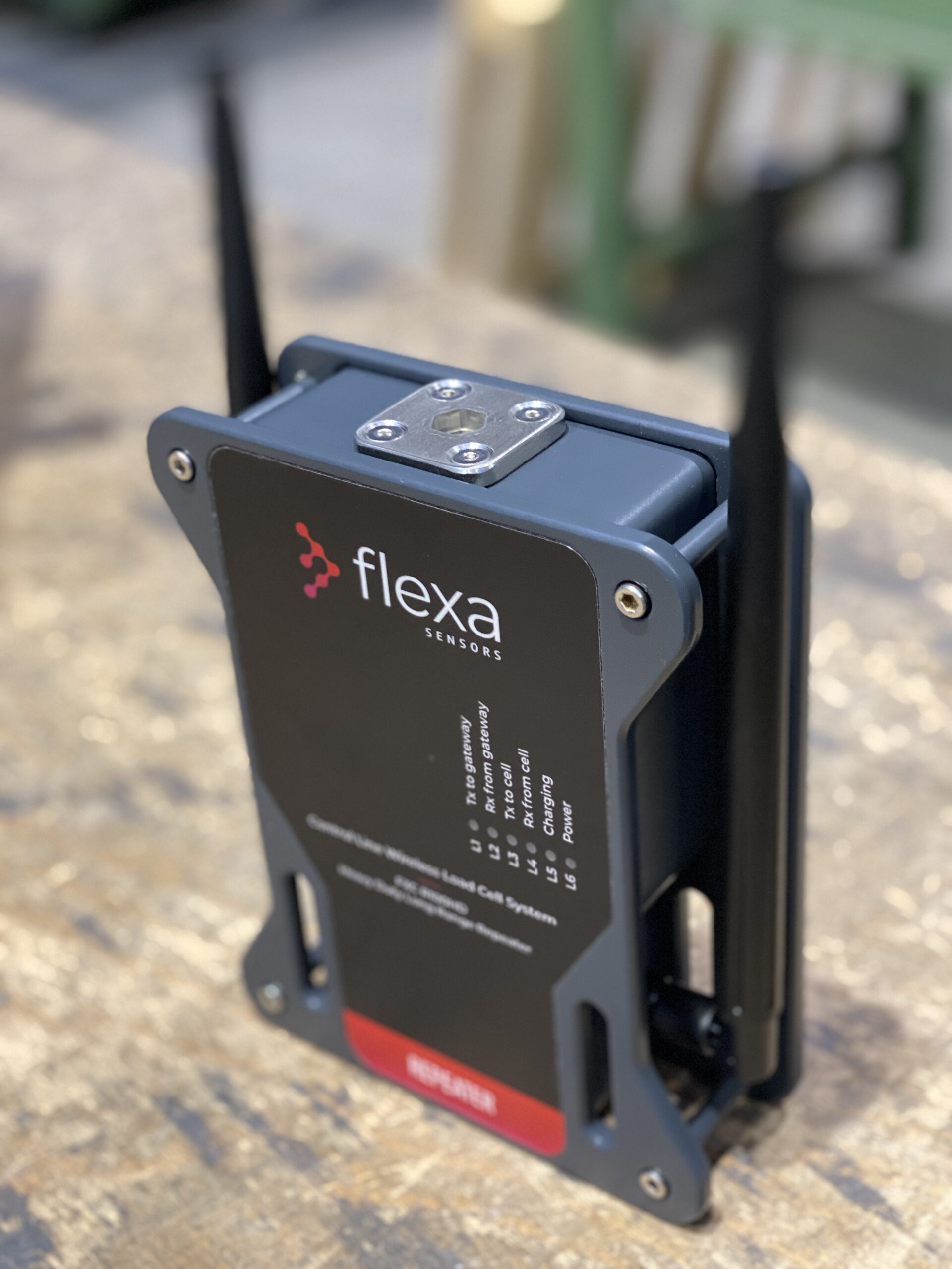
Six RGB LEDs constantly show the system status.
- L1: Tx LED is blue when transmitting
- L2: Rx LED is green when receiving
- L3: Tx LED is blue when transmitting
- L4: Rx LED is green when receiving
- L5: Charging LED – Red / Yellow Red – Low Battery
Yellow Blink – Charging
Solid Yellow – Fully Charged - L6: Power LED – Red / Cyan
Red – AC Supply Disconnected
Cyan – AC Supply Connected
DESIGNED FOR THE STAGE
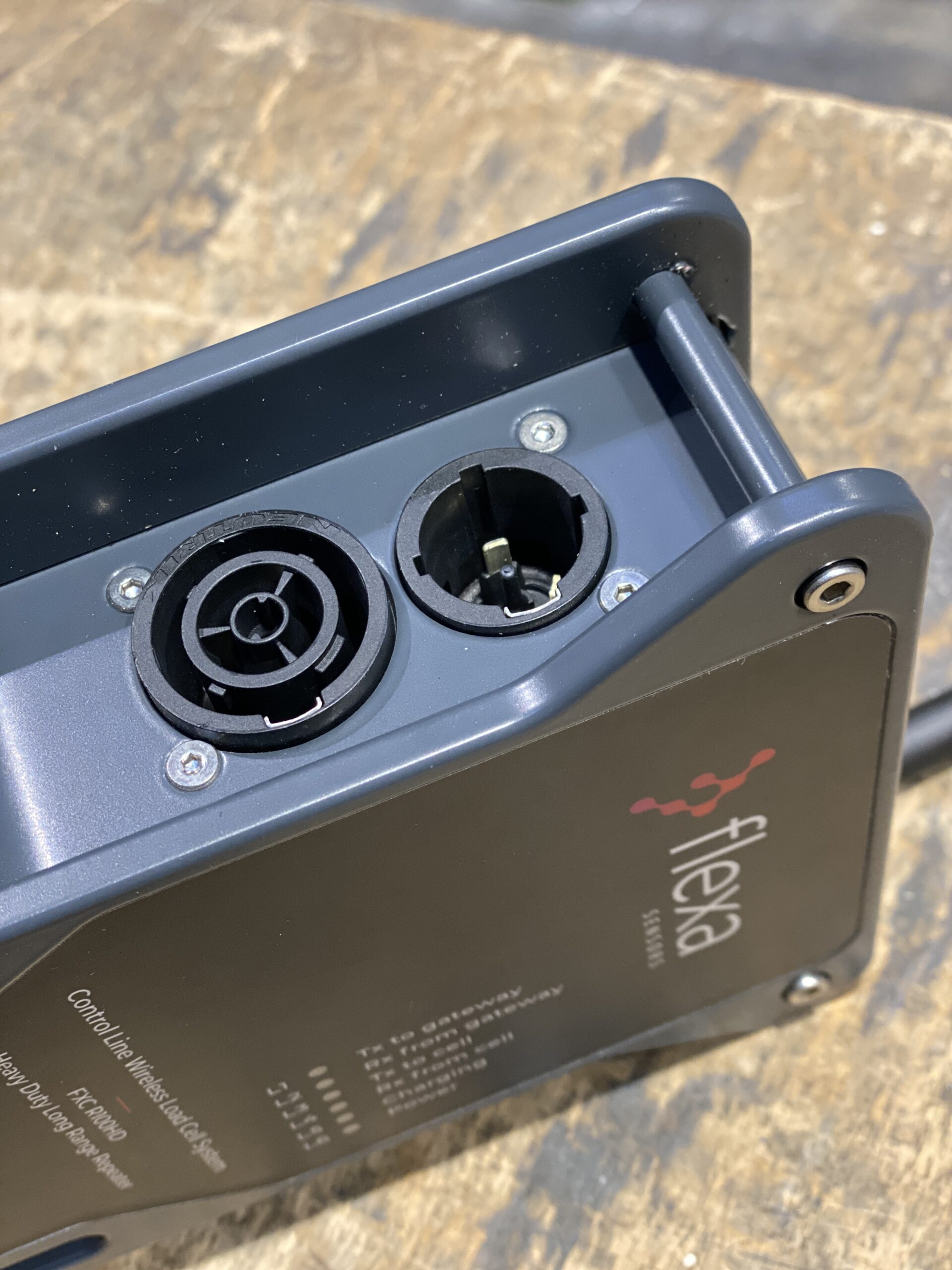
Easily positioned with clamps or ties. PowerCON TRUE1 inlet-outlet connector and backup battery to guarantee operation even in the event of a temporary power failure. One antenna for communicating with the cells and one for connecting to the Gateway.
REPEATER SPECIFICATIONS
5 unit
2.6Ah 18650 Battery
Up to 600m (line-of-sight)
Up to 700m (line-of-sight)
Sub-1GHz
Up to 100 hours
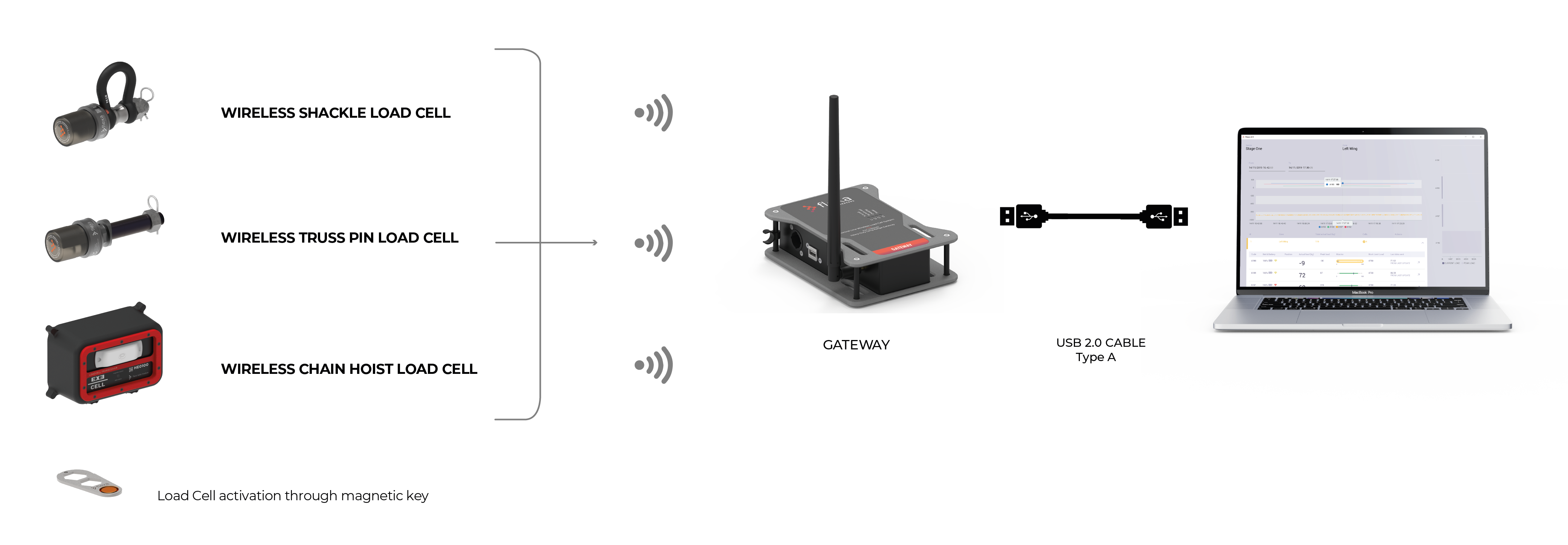
Plug & Play (no radio set up)
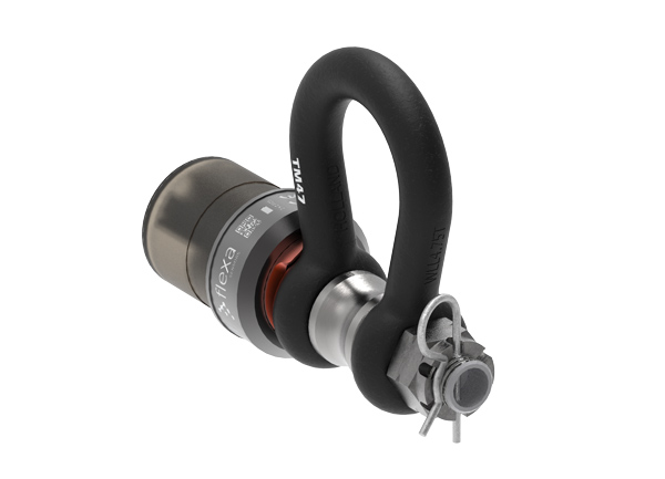
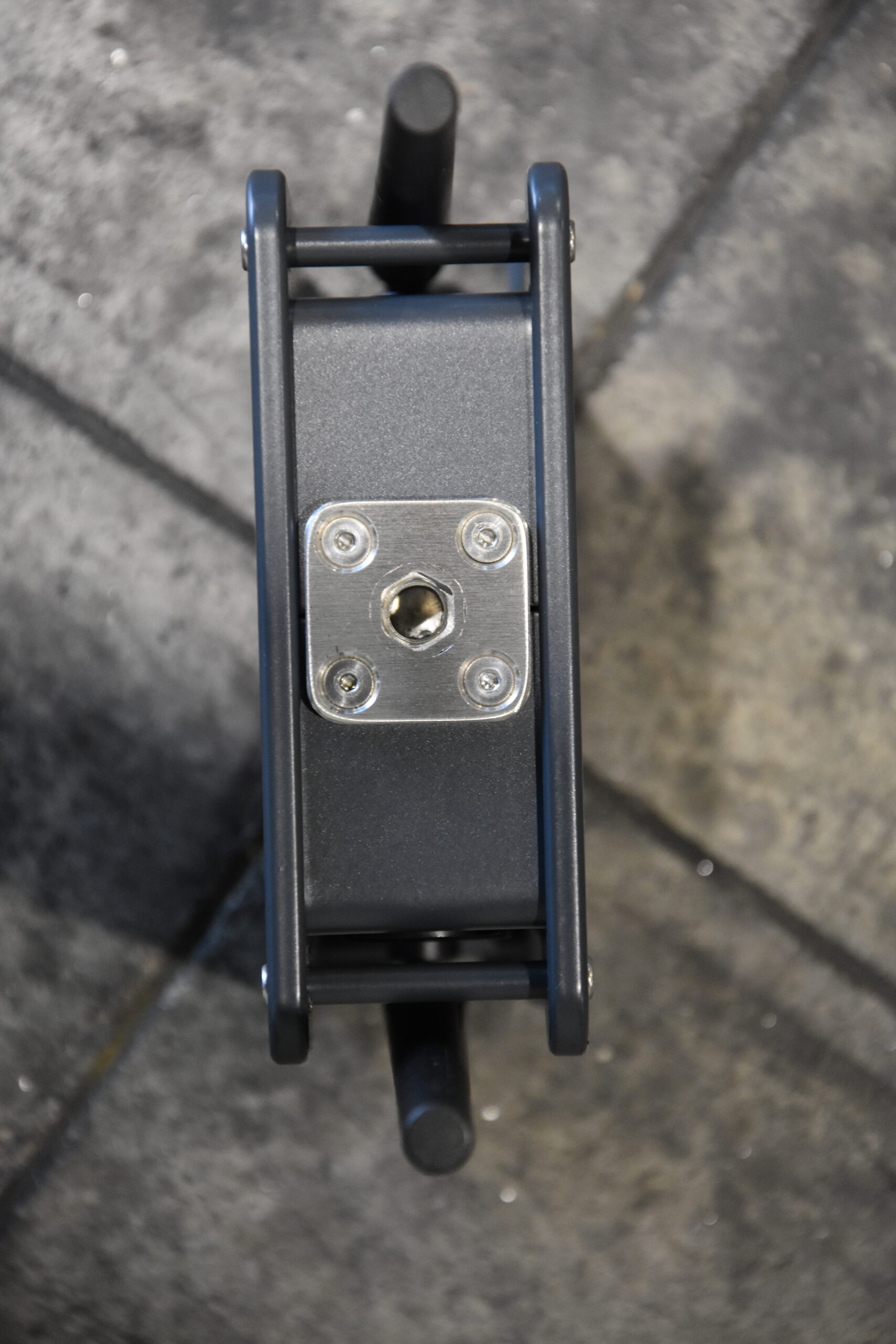
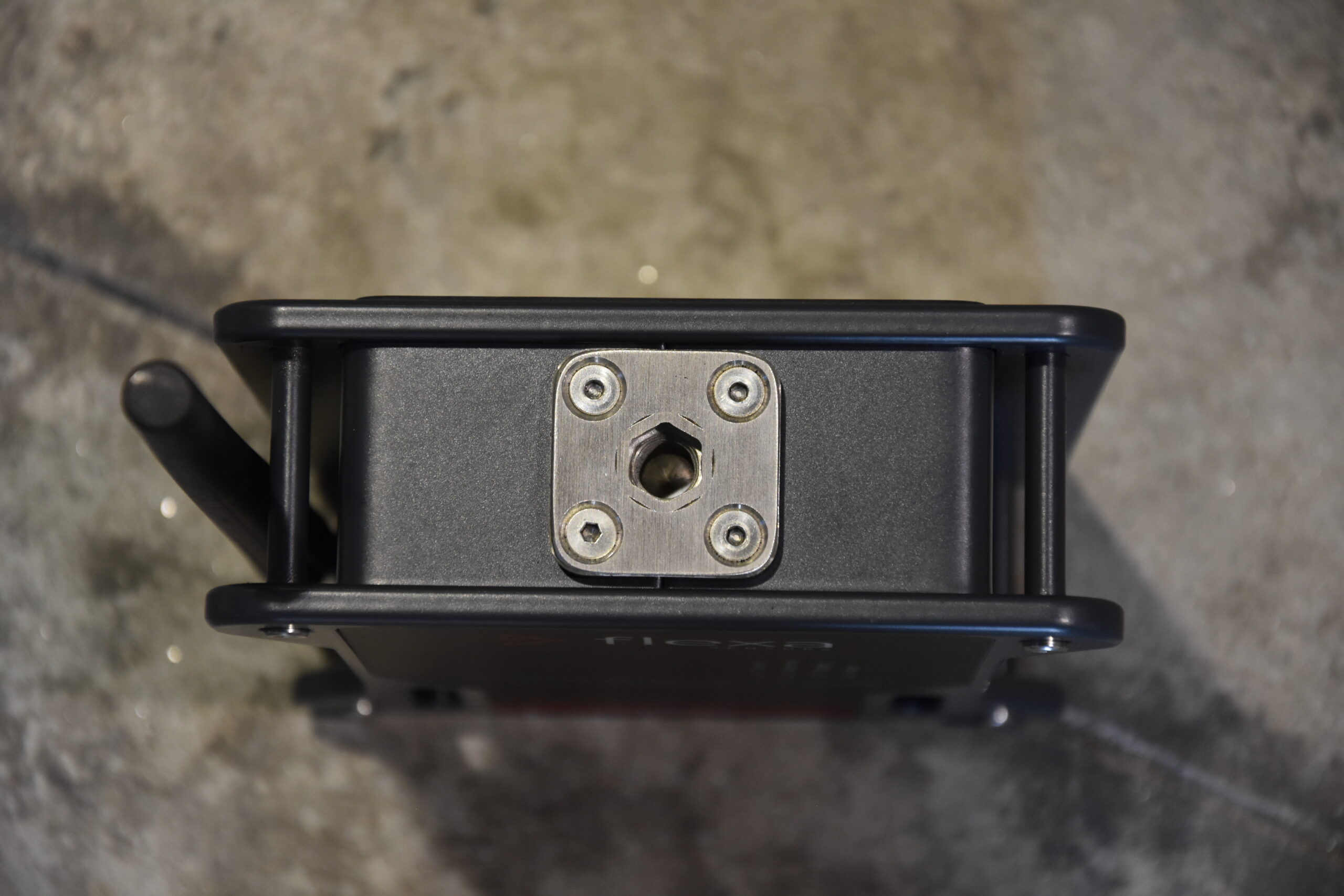
to better interface with truss clamps
WHEN IT IS NEEDED
All radio systems are affected by the surrounding environment. In most set- ups it is not necessary to use the Repeater. However, it is advisable to always have them available whenever the conditions of the location make it necessary. If one or more Repeaters are used, all the cells connect to the Repeaters and each Repeater connects to the Gateway (max 5 Repeaters per Gateway). In this option the Gateway does not connect to the cells directly.
SHORT AND LONG DISTANCES
In most common uses, the Gateway connects directly to active cells. In critical conditions of radio signal transmission, it may be necessary
SIGNAL QUALITY AND TRANSMISSION RANGE
Every radio transmission is affected by environmental conditions. The distances calculated in line of sight on an open field are different from the real ones in presence of different obstacles. The graphs below show different ranges based on the environment in which the system operates.
TUTORIAL VIDEOS
OPERATIONS OVERVIEW
POWER ON REPEATER
How to power on the Repeater with the Magnetic Key
CHARGING CABLE FOR REPEATER
How to connect the charging cable to the Repeater
Gallery
ASSEMBLED IN ITALY BY
Area Four Industries Italia S.r.l.
- www.areafourindustries.it
- info@areafourindustries.it
- VAT Number: IT 02748570245
- @flexasensors
- @flexasensors
- flexasensors
Enter your e-mail address in the box below to subscribe to the Flexa Sensors newsletter.
Your personal data will be processed according to the privacy policy.