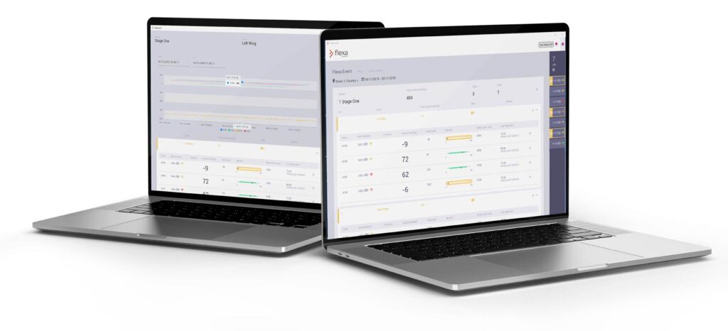

The need for live load monitoring and reporting is increasing in all industries, not only entertainment related, in order to provide a safer working environment.
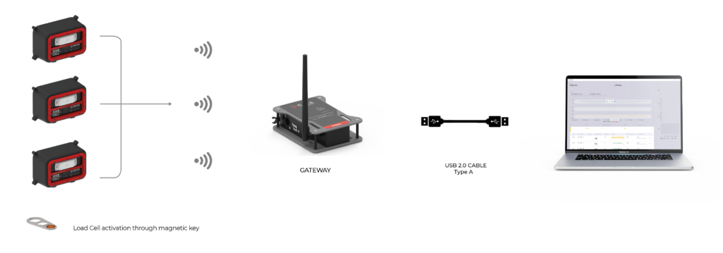
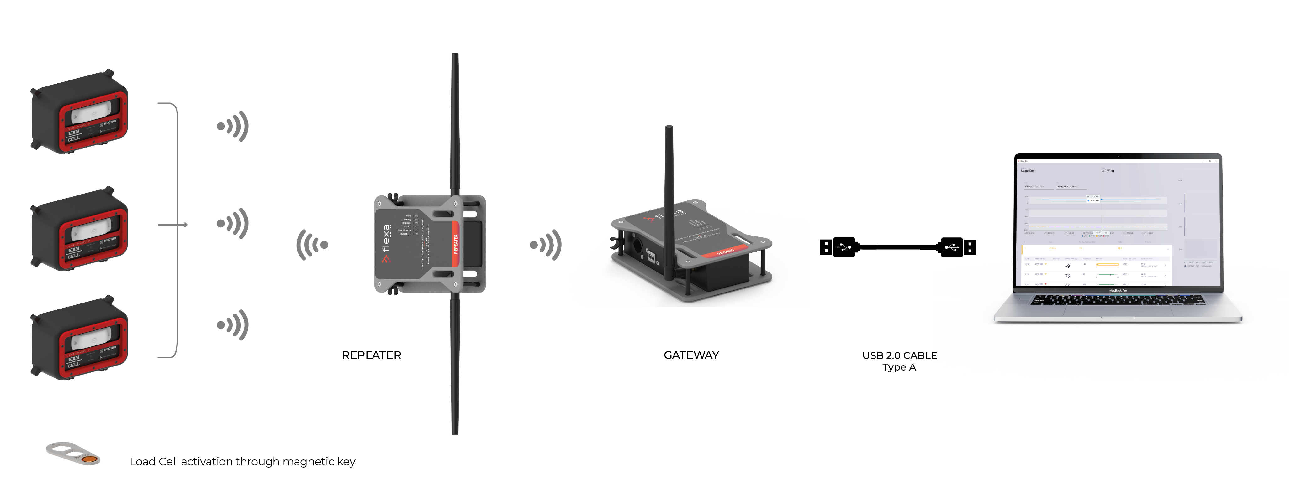
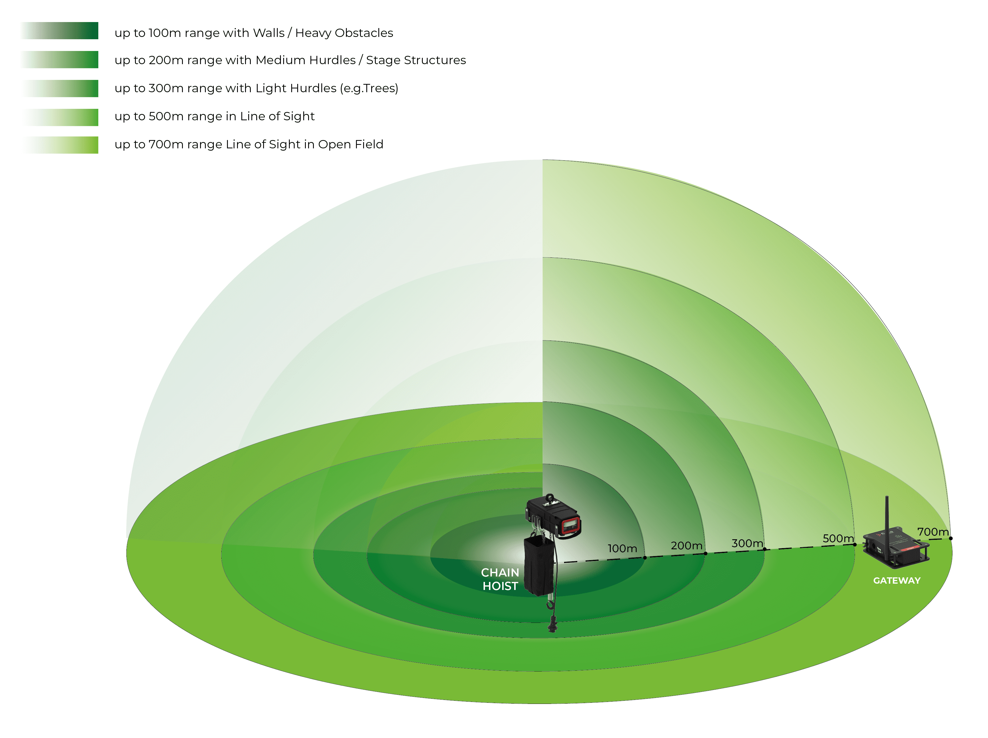
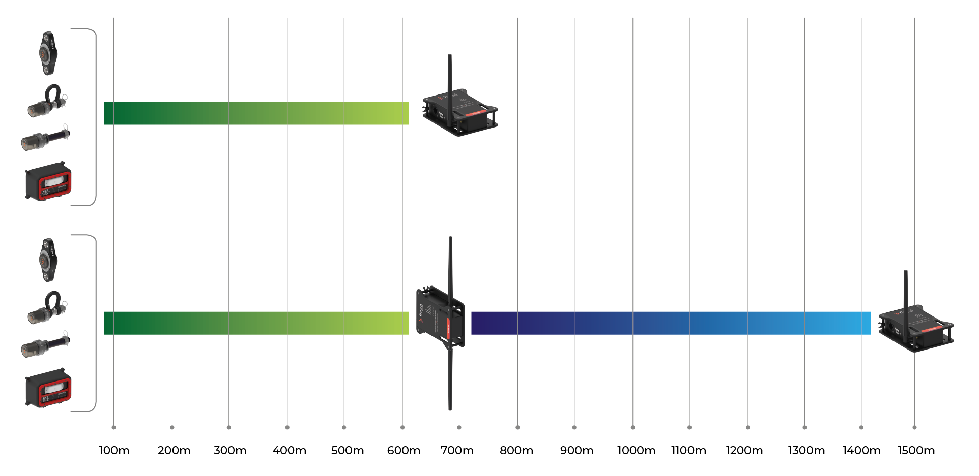
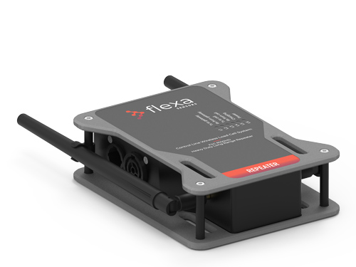
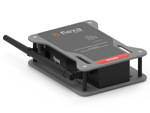
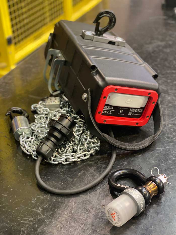
The joint work between FLEXA and EXE TECHNOLOGY product development teams resulted in the integration of the Flexa Sensors platform on board the EXE RISE hoists. This wireless technology applied to electric chain hoist offers maximum freedom in handling hoists, covering distances up to 600 meters from the Gateway.
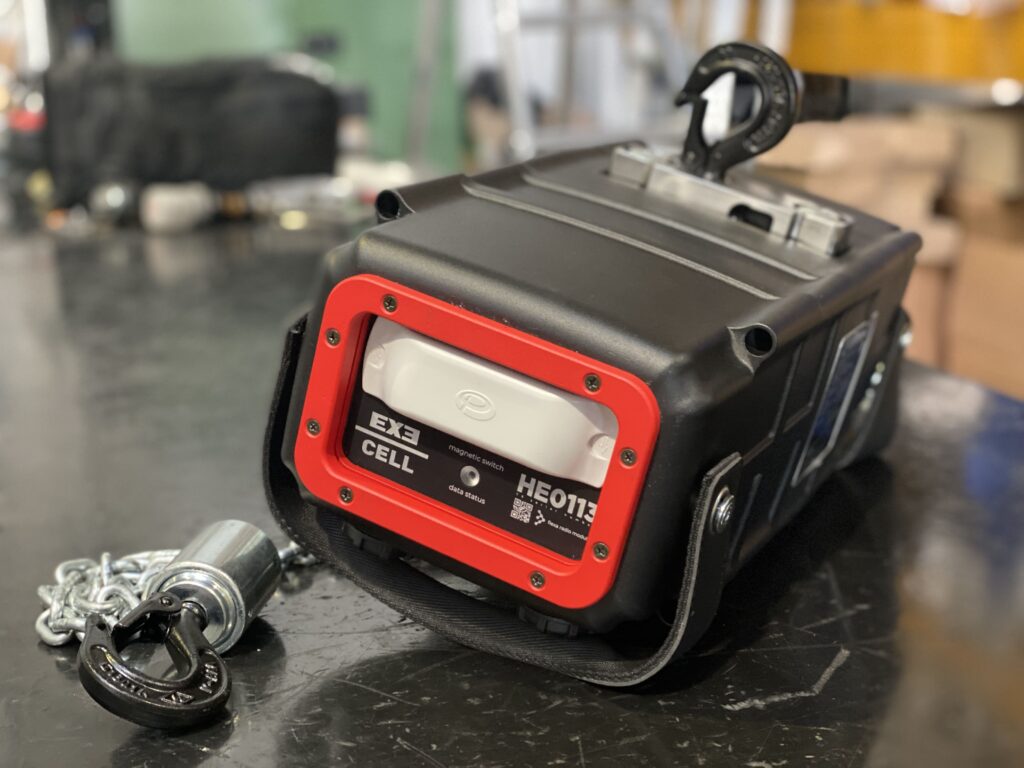
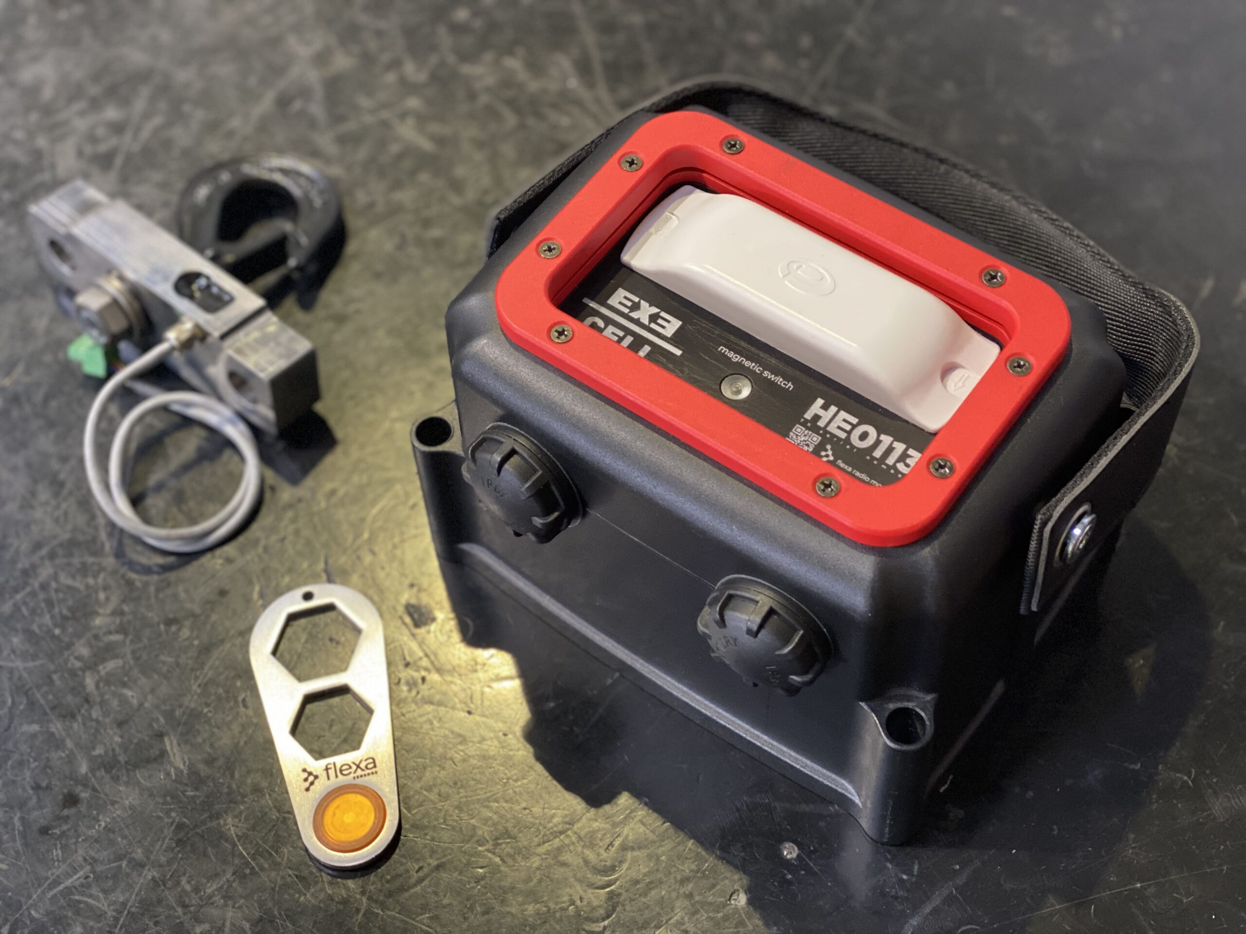
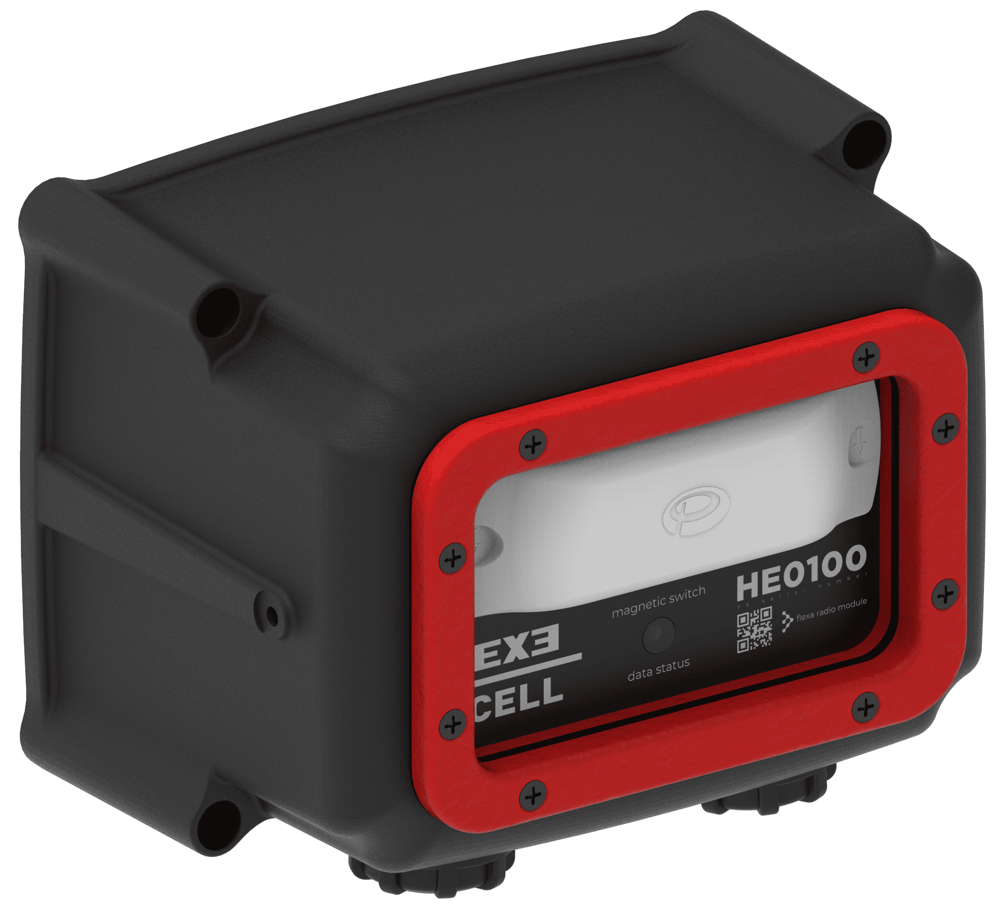
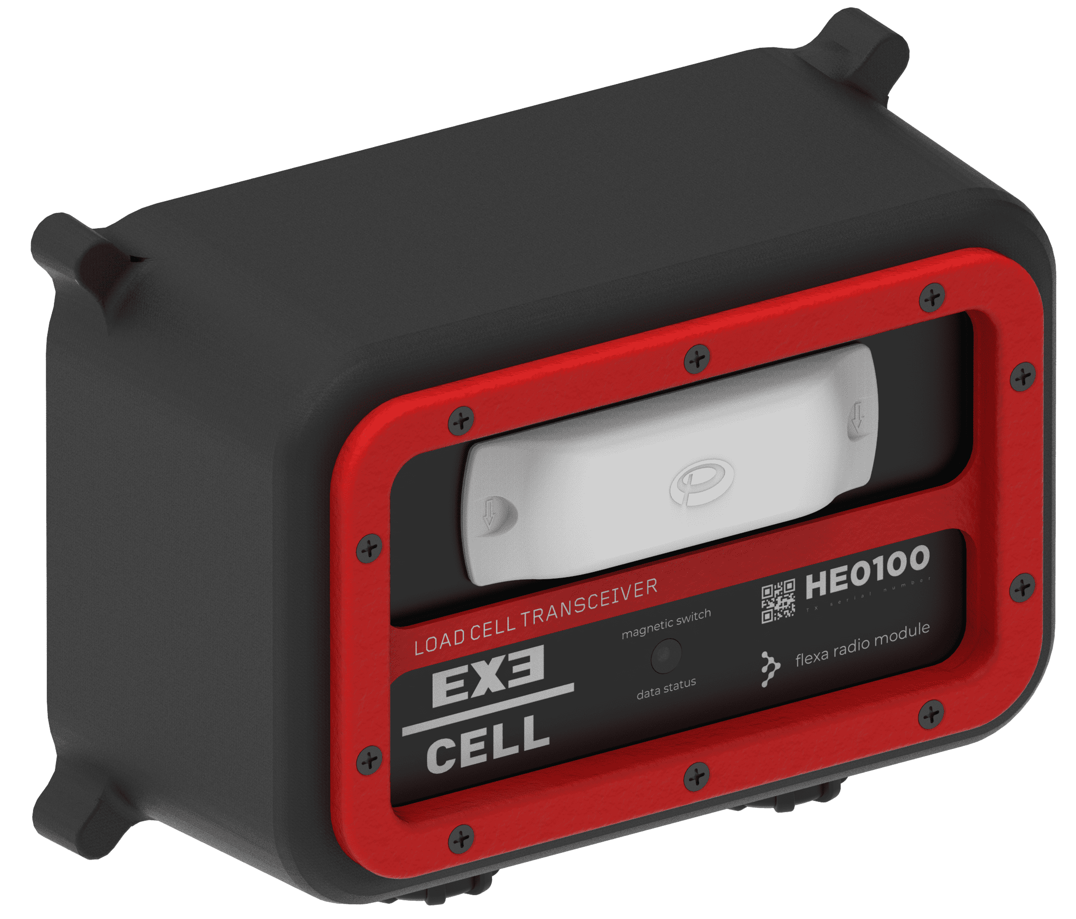
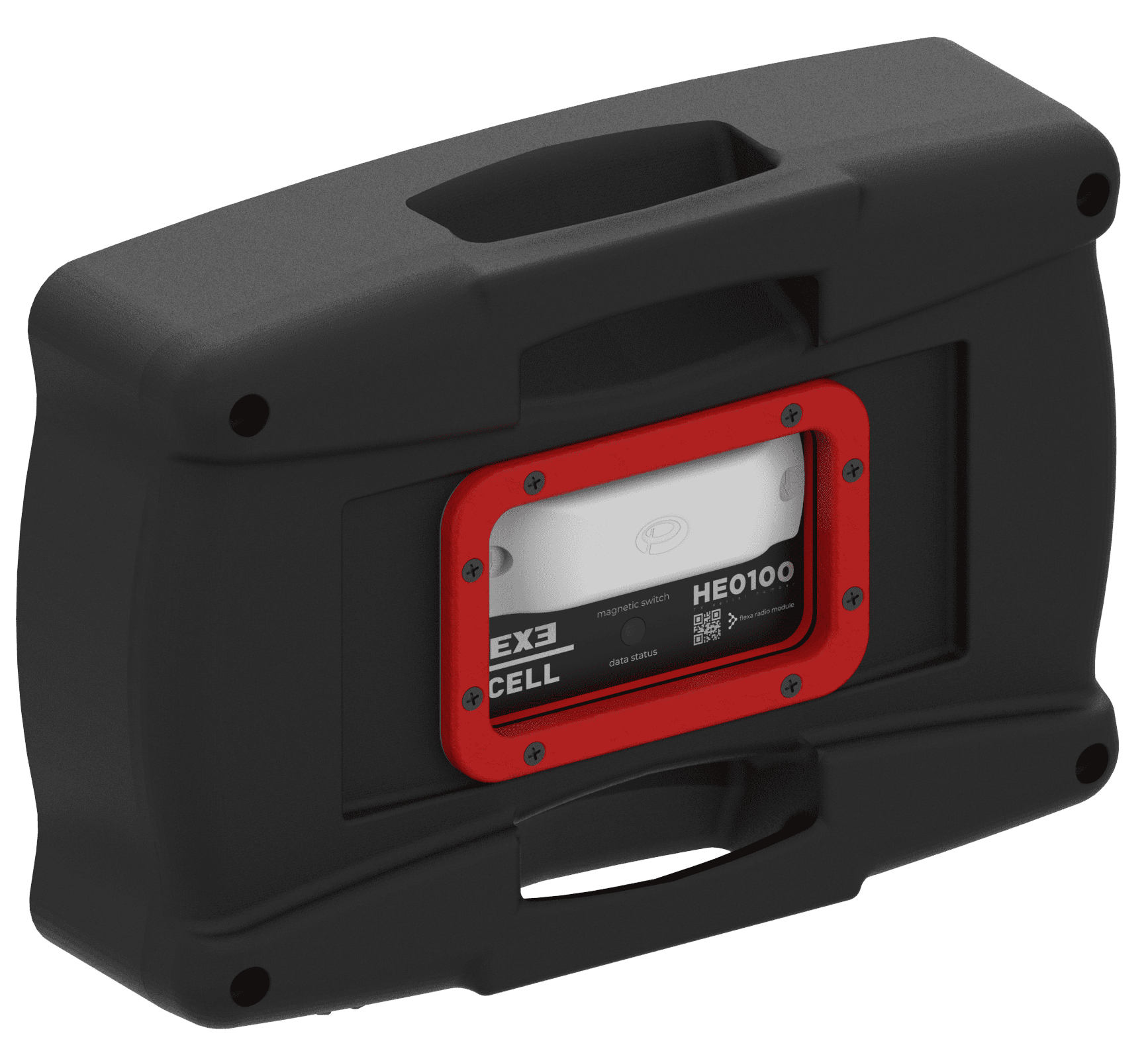
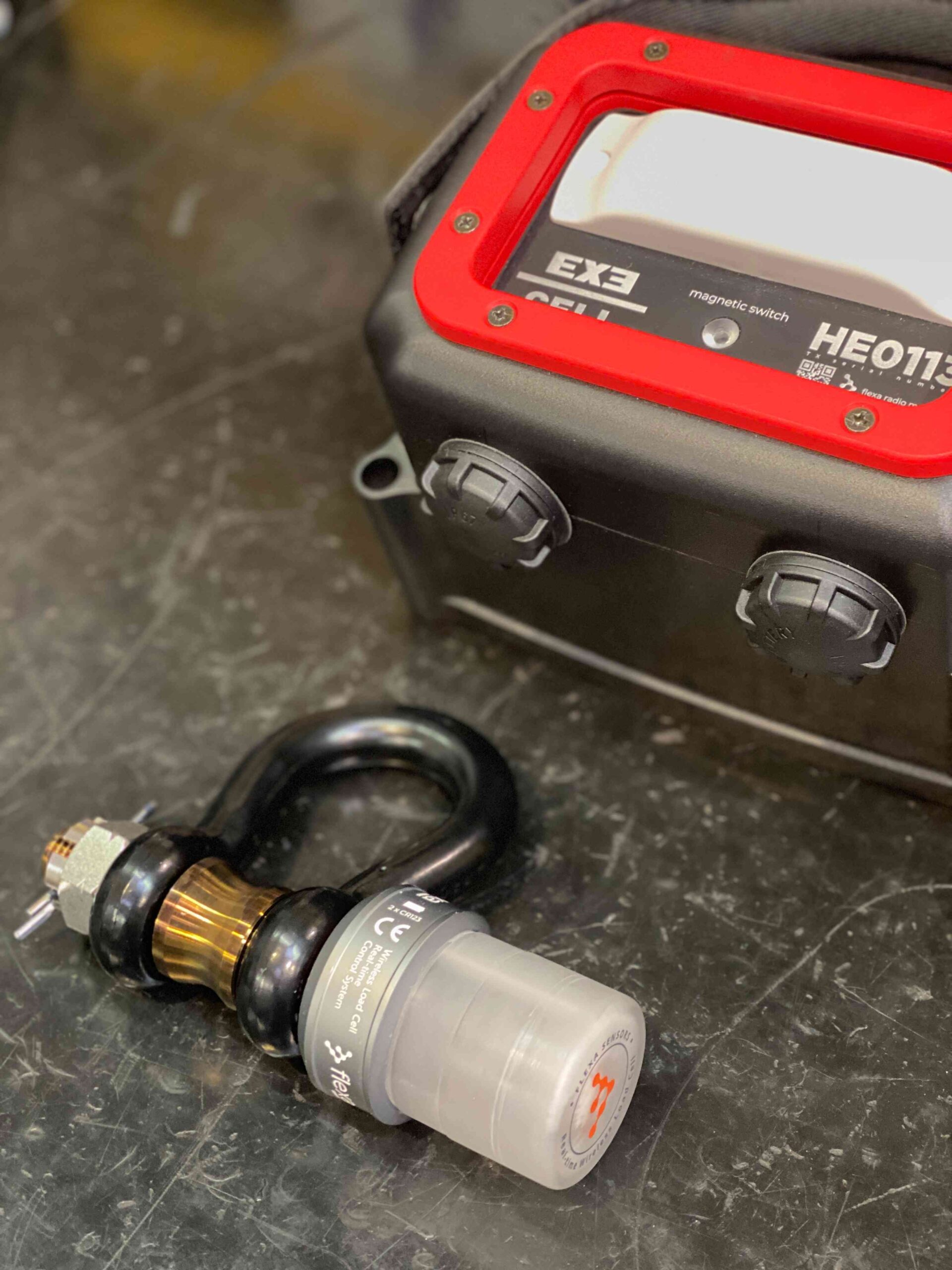
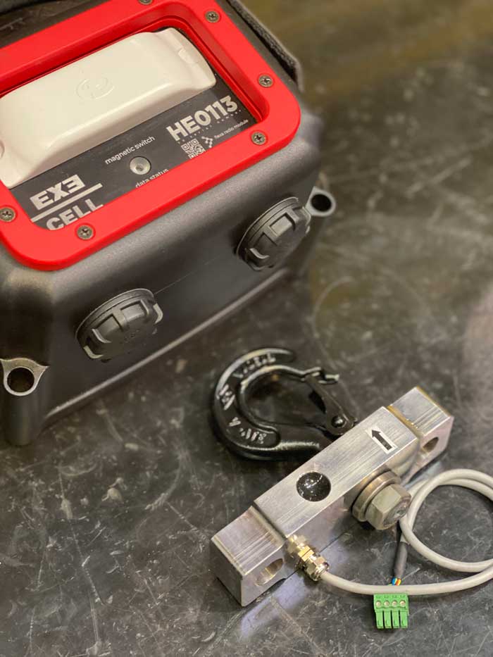
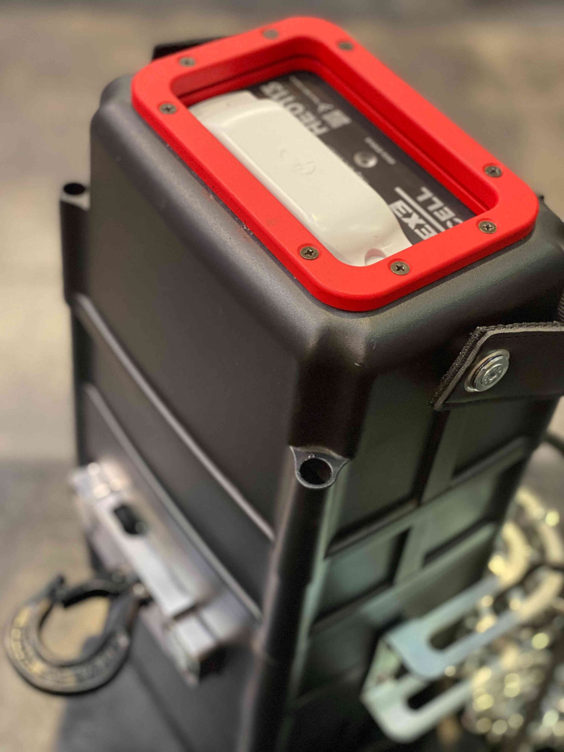
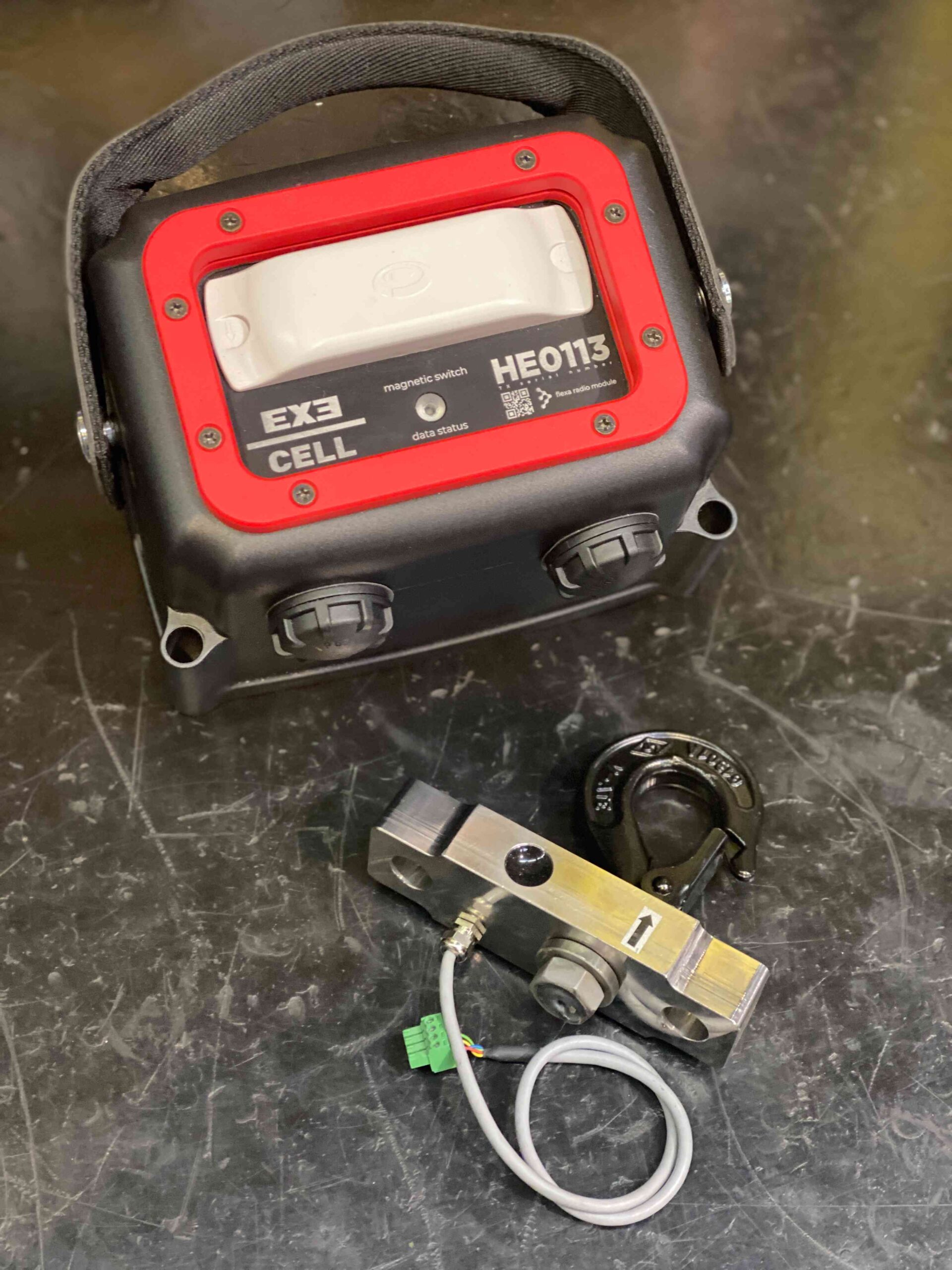
The Flexa module with the microprocessor and the radio section is mounted on one of the two hoist side covers. The externally mounted anti-shock antenna offers a high degree of efficiency even in difficult conditions for radio waves, such as in stage roofs. The module is connected to the EXE CELL system which integrates the load cell inside the motor hook of the EXE RISE chain hoists. The final result translates into a unique design and an unparalleled practicality of the product in the daily use.
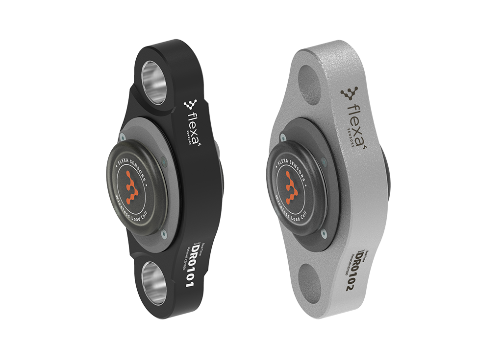
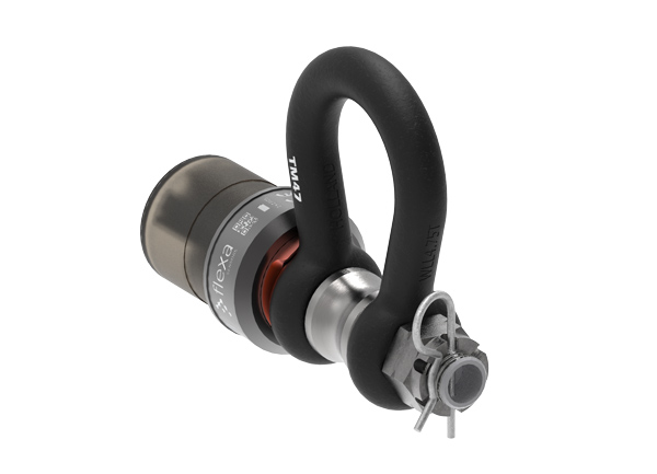
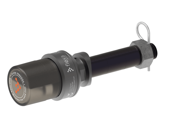
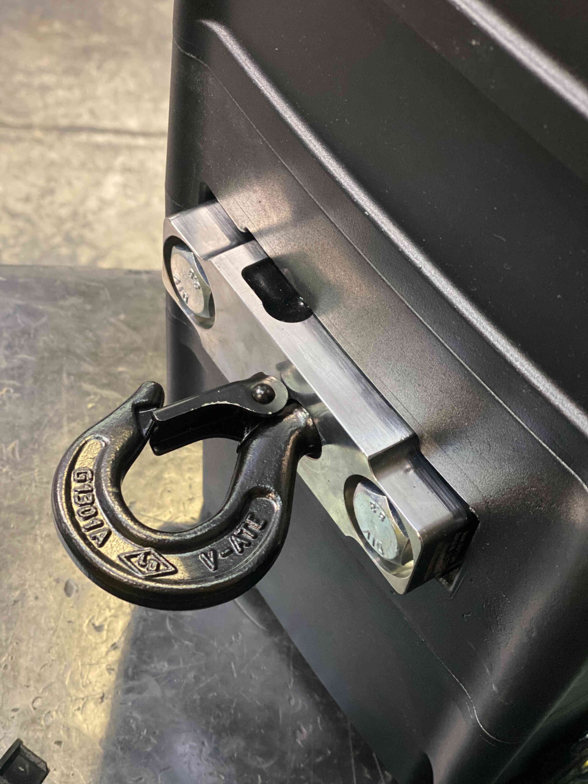
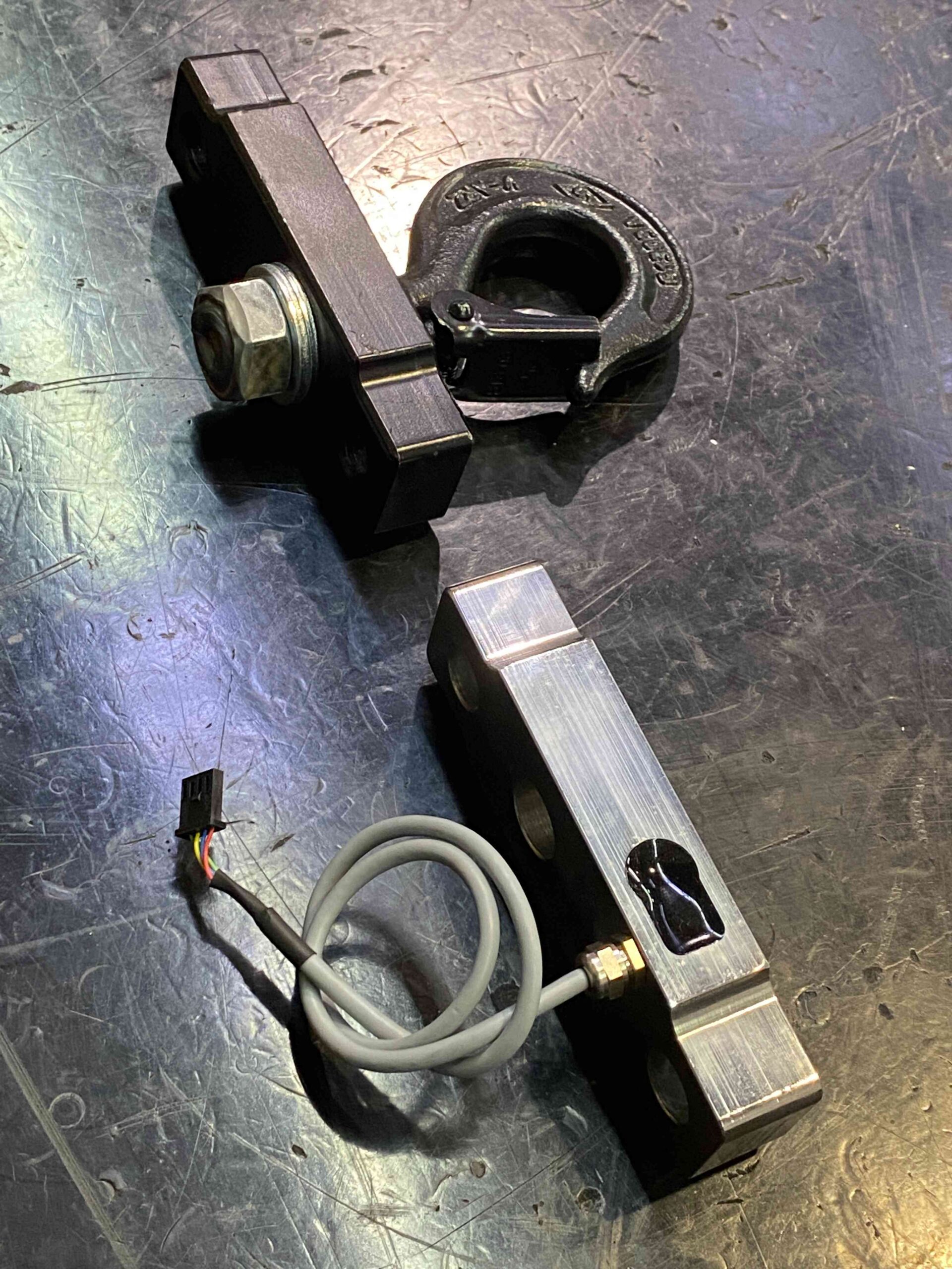
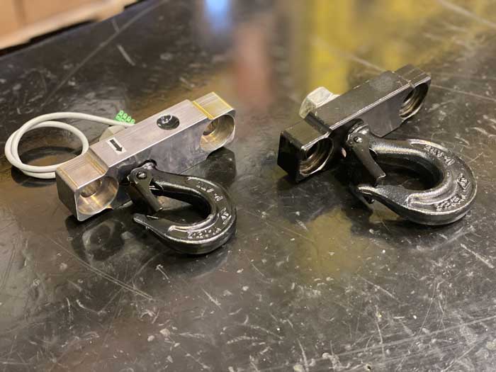
This emblematic image shows how the load cell can be integrated in the steel block that connects the electric hoist to its “body” support hook, thus eliminating external wires without losing any space in height compared to a solution based on an external cell… a true masterpiece of technology!
From a standard EXE hook
Built to withstand the demands of touring
Fully integrated load-cell in chain-hoist hook
Between hoists and gateway 600 meters approx (additional repeaters can be added to further extend rangeB
Under the front panel for a high IP level. (the magnetic Reed is used to switch the cell module and radio transmission on and off and is independent of the hoist power supply)
Max No. of hoists (or cells) per system 100 units
Every 1 second
Every 1 second
According to the load status (when the load stabilizes, the rate decreases)
Automatically switches off in case of long inactivity to reduce battery consumption
Sub-1GHz
Can be easily set by the operator
Are powered with four C batteries to guarantee long lasting life (up to several years) with battery-saving smart transmission
With Flexa Wireless Load Cell System
Of Load Cell for easy setup without dismounting the hoist
Four C (R14) batteries to guarantee long lasting life (up to several years)
Are needed to access the batteries, all you need to do is un- screw the cap of the battery holders
Smart transmission strategy: it transmits every second when the load change exceeds a configurable threshold, transmits less often when the load is stable keep on reading every second
Multifunction RGB LED
Area Four Industries Italia S.r.l.
Enter your e-mail address in the box below to subscribe to the Flexa Sensors newsletter.
Your personal data will be processed according to the privacy policy.