


Not a simple data conveyor but an intelligent machine that constantly communicates with cells or repeaters.
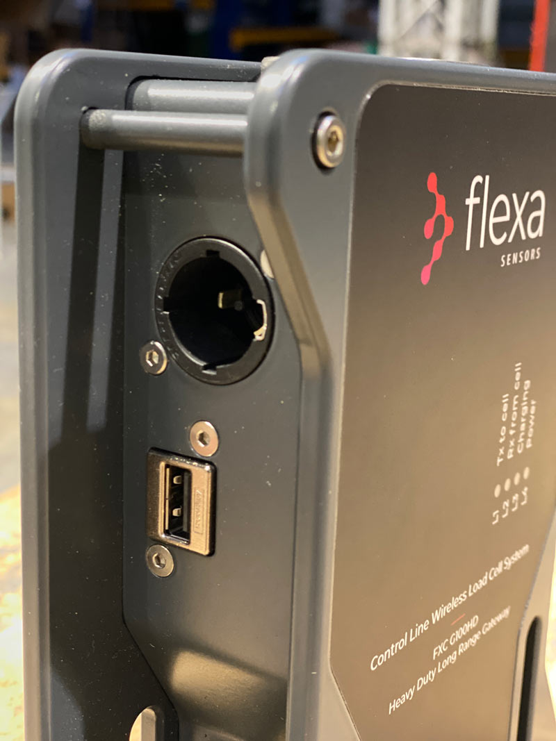
The active cells must constantly communicate with the Gateway which must always be on, even in the absence of a PC. When connected to the PC it is powered via USB. Without the USB cable, the internal backup battery takes over. For long periods without connection to the PC, the AC 220 / 125V input with PowerCON TRUE1 connector is available.
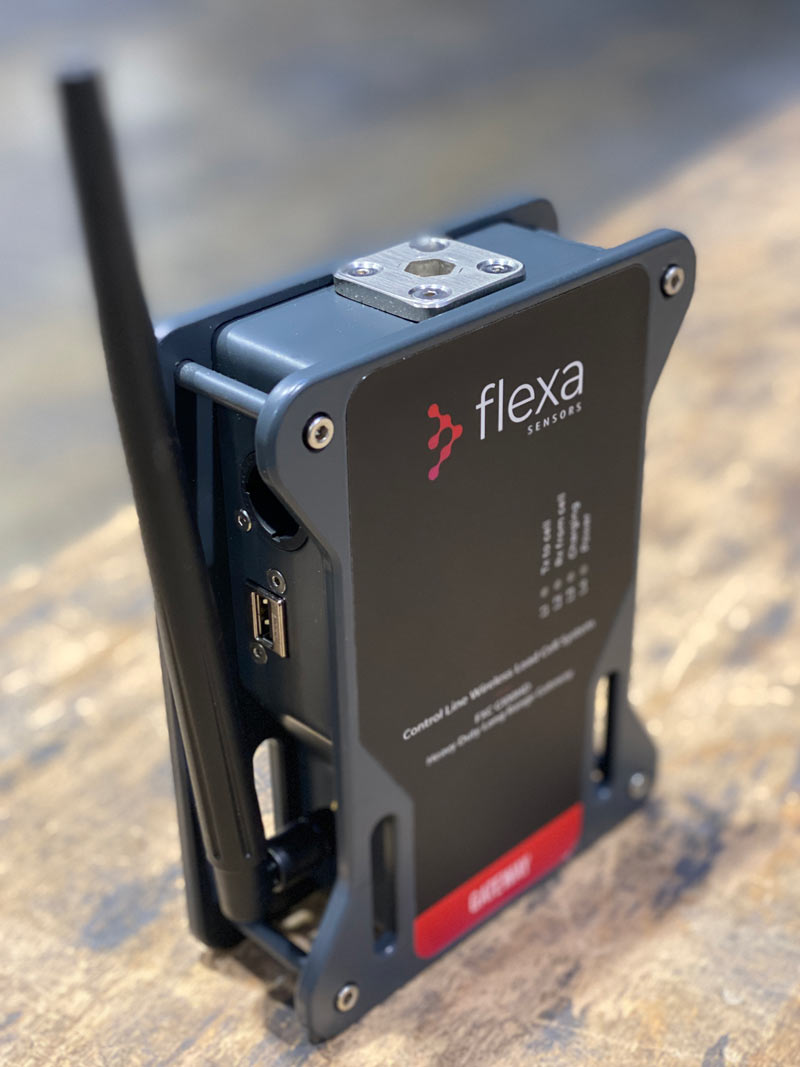
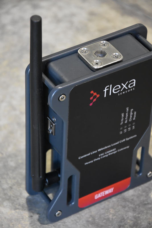
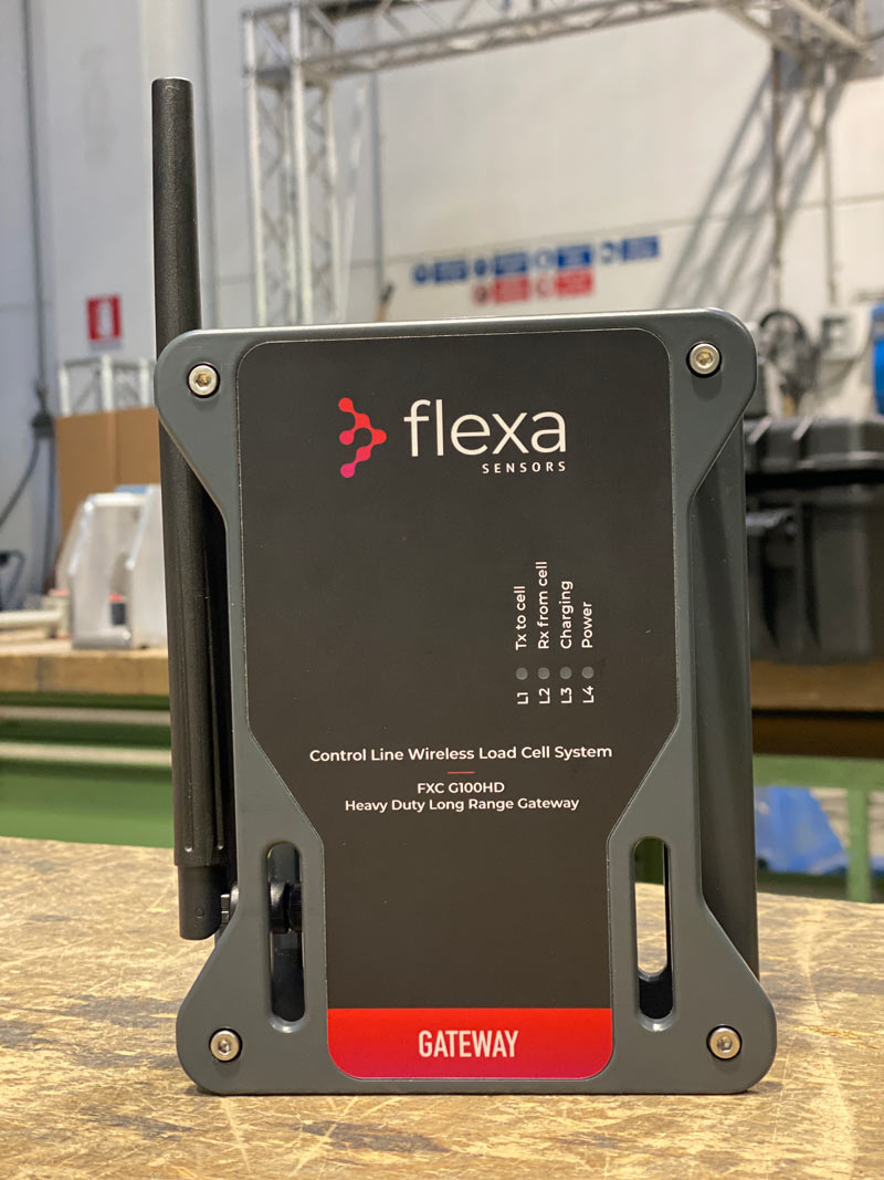
Four RGB LEDs constantly show the system status.
L3: Yellow only when AC supply or USB supply is connected: Blinking Yellow = Charging
Solid Yellow= Fully Charged
Red = no external power supply is connected (AC Power Supply or USB Power Supply) and battery is Low
L4: Cyan LED blinking when AC supply connected, Red blinking in all the other cases (it means USB supply or Battery Supply) (it is like an ON/OFF indication)
100 unit
5 unit
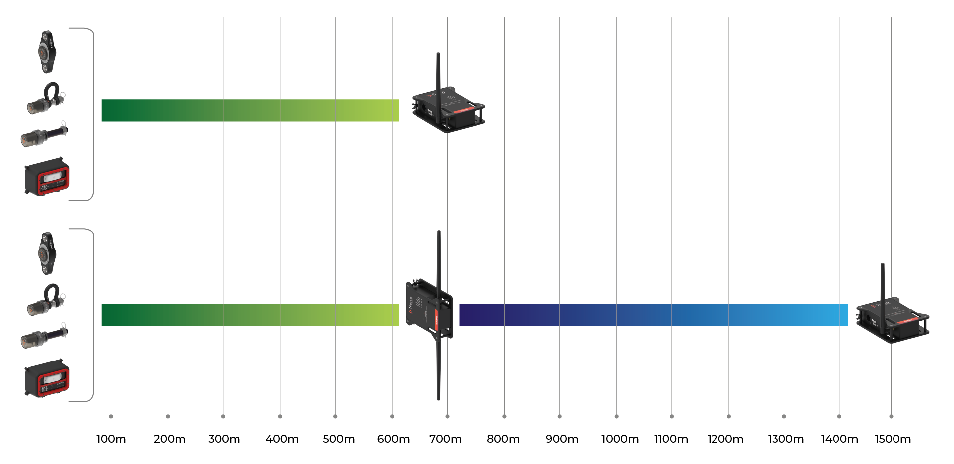
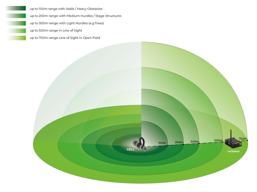
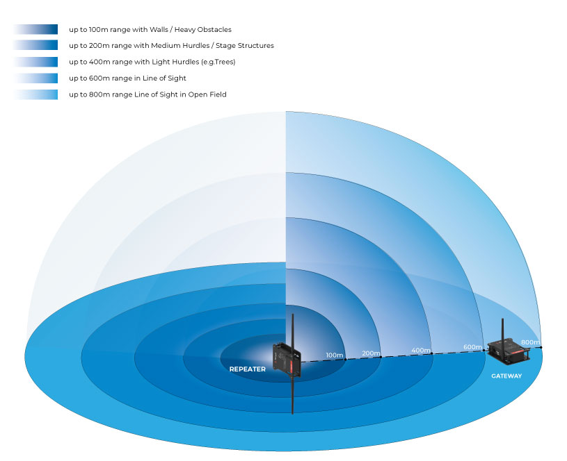
Up to 600m (line-of-sight)
Up to 700m (line-of-sight)
Up to 100 hours
Sub-1GHz
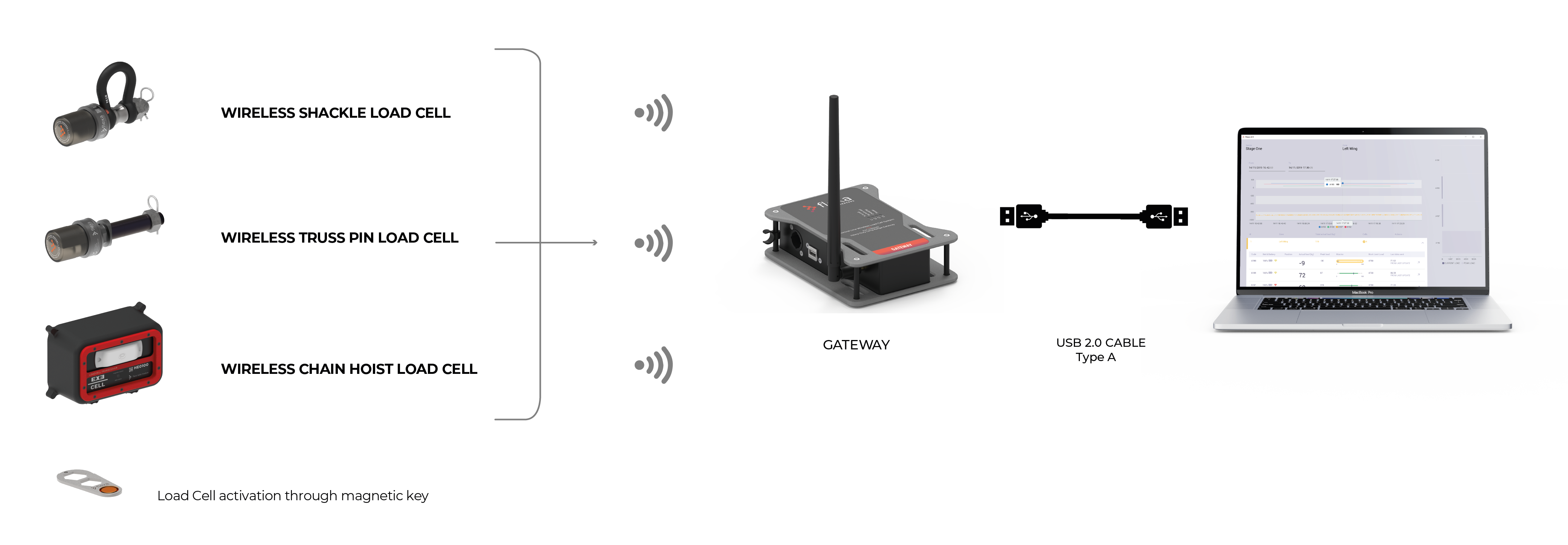
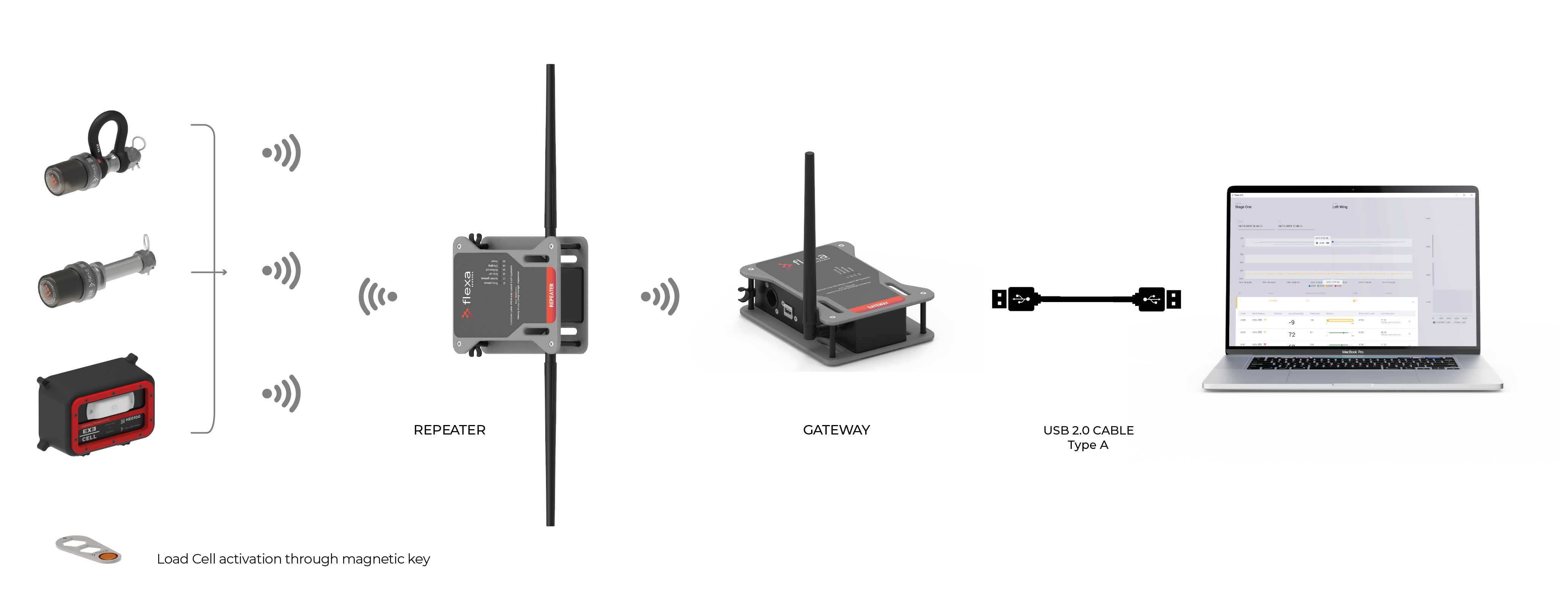
Local PC (connected to gateway via USB-A cable)
Sub-1GHz radio connection
Plug & Play (no radio set up)
2.6Ah 18650 Battery
to better interface with truss clamps
How to power on the Gateway with Magnetic Key
How to connect the charging cable to the Gateway
Area Four Industries Italia S.r.l.
Enter your e-mail address in the box below to subscribe to the Flexa Sensors newsletter.
Your personal data will be processed according to the privacy policy.